|
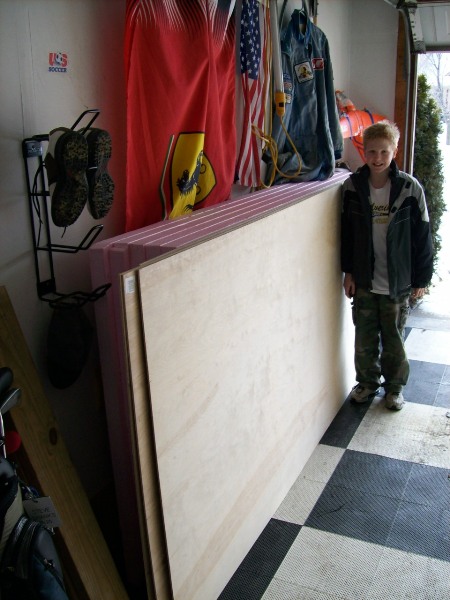
To start the layout process, we went to Home Depot in a friend's
truck (since I only own cars) and picked up 5 foamular 4x8x2" boards
plus 5 matching 1/4" birch plywood boards. Plus about 130 feet of
1x3 and 1x2 select pine.
And....
Liquid nails for projects and DAP Weldwood contact cement
And a couple of hundred screws.
And....
A saw for cutting the foamular board. Later on, I went back and
bought a miter saw as well as a cordless drill, since mine had batteries
that no longer held much charge. I have a Bosch power drill and the
cordless will be used for screws.
|
|
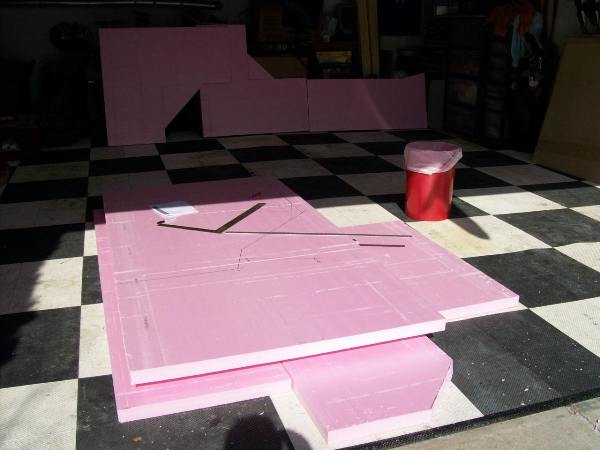
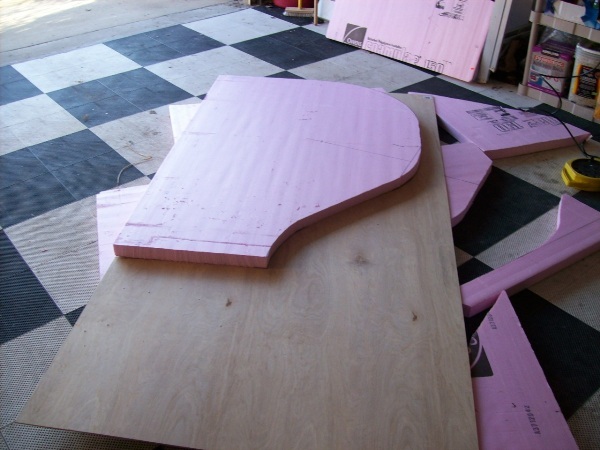
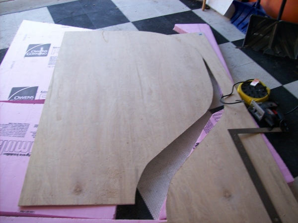
We did the cutting in the garage. It was about 25 degrees but with
no wind and the sun out, it wasn't too bad. At the back, we've already
cut out pieces B, C and D. A is on the ground ready for cutting.
|
|
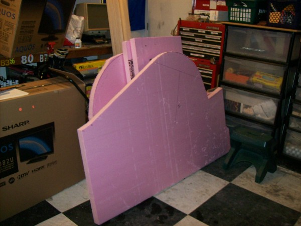
We've done all of the foamular board cutting. The curves are rough,
within an inch and I'll use a hot wire cutter to do the final cut.
|
|
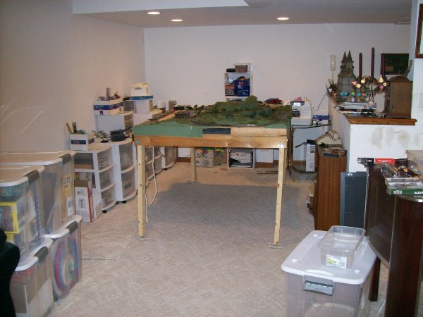
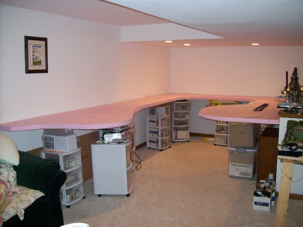
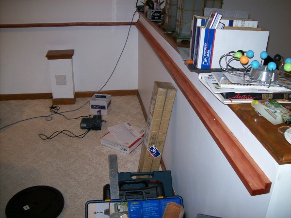
This is the corner of the basement where the layout is going to go.
At the moment, my train collection boxes, our prior layout
(GS & SV RR),
my wife's sewing machine and various supplies take up the
space.
But not for long.
|
|
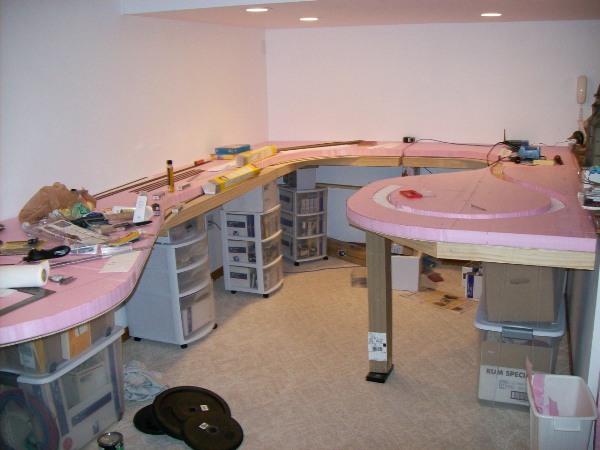
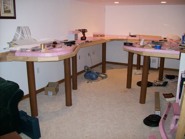
Here we have placed the foamular board in the first trial fit. The
pieces A, B, C, D & E are in place, in the photo from right to left in a
counter-clockwise direction.
For an idea of scale, the width of the
area is about 9 feet and the narrow point of the aisle is 3 feet and 5
feet wide at the far end. Plenty of room for Simon and myself to
operate. The length on the left side is 15 feet.
|
|
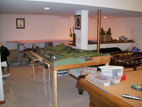
A view across the east end of the basement, with the GS&SV layout
awaiting extradition from the basement.
|
|
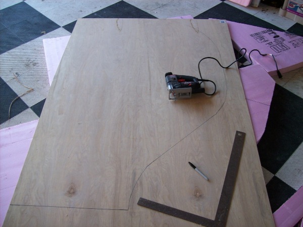
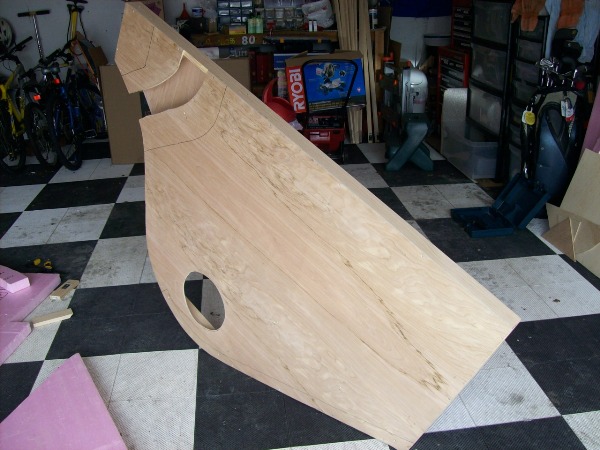
Having already cut the foamular board, it's now time to create the
birch plywood base for each. I simply laid the foam board onto pieces of
the birch plywood and drew around them. Then I cut them out with a saber
saw.
|
|
Here's the saw ready to go. You can see the lines for cutting. I did
use a straight edge and set square where appropriate. When I said draw
around the foam it was a generalized statement. The actual execution was
more accurate than that.
|
|
And piece A is cut out.
|
|
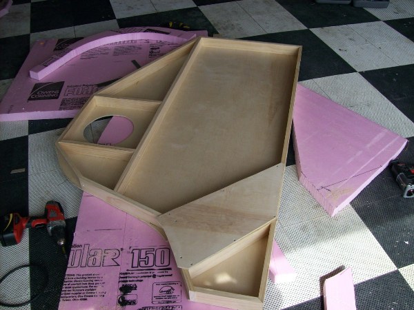
Then I framed each piece of the plywood with what Home Depot calls
"select pine". This is 1"x3" select pine. It will give the base some
rigidity and will allow a firm surface for mounting on the wall as well
as on which to mount a fascia.
|
|
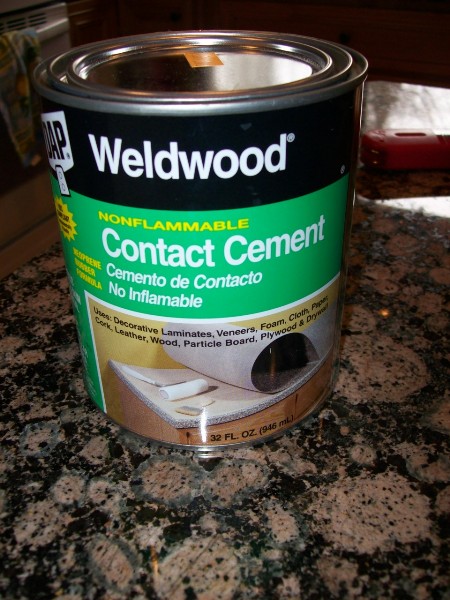
Here's the DAP Weldwood Contact Cement. I'd never used this
before. I used it to glue the foamular board to the birch plywood. You
apply it to both pieces with a paintbrush, wait 30 minutes and press
them together.
Make sure you get it right first go because the directions say 75
lbs/square inch (or something like that) is needed to get the glued
things apart.
I managed to do the first 4 (pieces A, B, C & D) without incident. I
did need help in positioning the foam before pressing it down on the
plywood. I would position one edge at one end, have the other end held
about 1" above the plywood, and then, when it was all lined up, drop it
down and press hard.
|
|
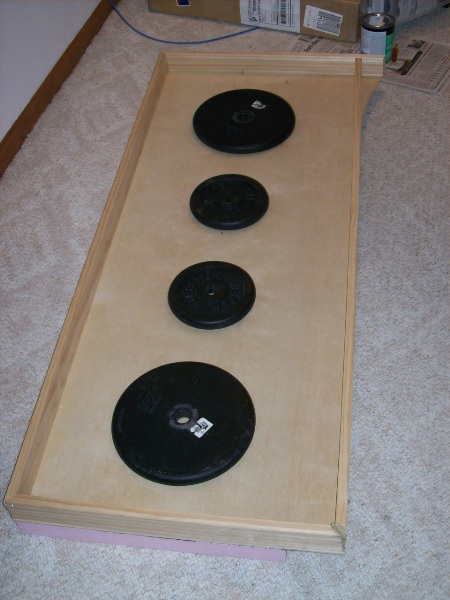
We have some weights lying around which I pressed into service.
Here, you see two 10lbs and two 25lbs. I also have a 50lb which I didn't
use on piece D as shown here.
|
|
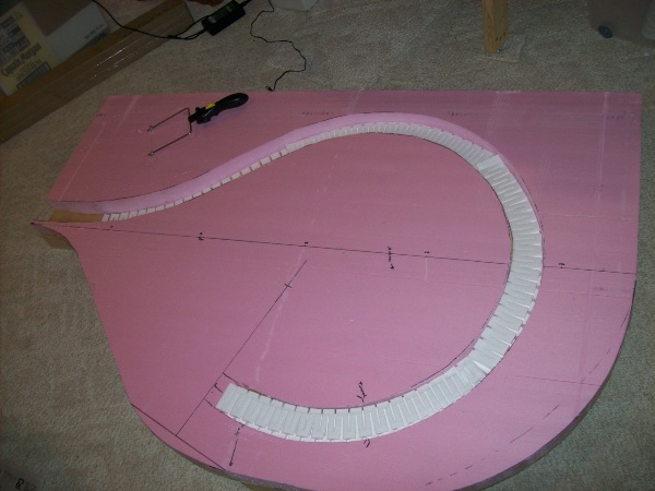
Here we have the 4th piece that I did. This is piece A (I did piece
D first then C and then B prior to this). This piece has a trench cut
out of it so that a 2% Woodland Scenic's 2% grade could be inserted into
it.
I cut the trench out with the saber saw and then used the Woodland
Scenic's hotwire cutter to smooth out the edges.
This is all test fit here.
|
|
Here we have pieces A-D with finished framing. Piece E is on the
left, which has still to be done.
|
|
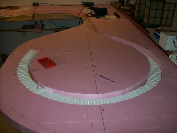
Here's a close-up. The foam is glued in but the Woodland Scenic's
grade is just test fit. The radius of this curve is 17" on my plan,
which is in the middle of this trench. However, I can run the track
closer to outside and likely get a 18" radius.
|
|
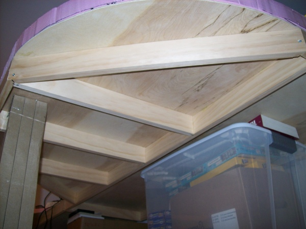
Here is the underside of that section. The framing is 1"x3" select
pine, all pieces are glued with liquid nails for projects and screwed
together with countersunk #6x1.5" wood screws.
This makes the piece quite rigid. Not for walking, but certainly for the task at hand.
|
|
Here is the underside of the piece E. The turntable spot has been
cut out and the river established. This piece is the largest. It is
almost 6' long and 3'9" wide at its widest.
|
|
Here is piece E from the top. The river is cut out and the banks,
which will have the D&H and maybe the CNJ are marked.
|
|
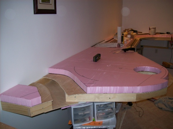
Here the piece has had the foamular board glued on. For an idea of
scale, the turntable opening is 9.875" in diameter (for the Walther's
130' turntable) and the river plain is 18" wide at the left and 16.5" at
the front/right.
|
|
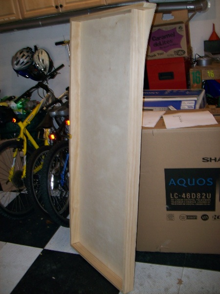
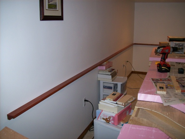
Next up was to create the mounting for the sections to the wall.
This is a L-shaped member made of two 1"x2" select pine pieces. This has
been stained with a cherry stain to match other wood (like the
baseboard) in the basement.
The sections will sit on the top edge and will be secured with clamps.
This piece is 15' long and was constructed from 6 pieces of 6' pine,
offset so that the joints are all in different places. The far end is
cut to 45 degrees in the horizontal plane.
The rail is secured to each of the joists along the wall. #6x1.5"
suffice for this purpose.
The piece at the far end is 8'9" long. Same construction.
|
|
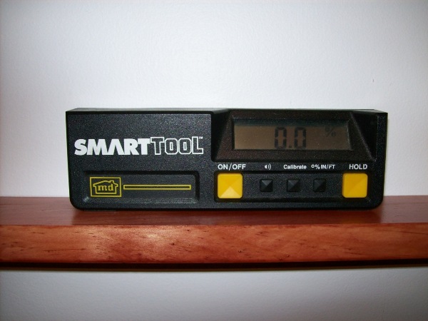
The SmartLevel from SmartTool is a tool for many uses. I originally
bought it years ago for adjusting the suspension on my track cars but
have found many other uses over the years. It is digital and measures to
0.1 degrees. Here you can see that I have got this pretty level !!!
|
|
On this wall, the 9'6" piece is constructed upside down. The reason
for this is to force the sections A and B away from the wall by the 3/4"
of the 1"x2". This is so that the sections clear part of the molding on
the shelf.
Nevertheless, the surface on which the sections rest is
level with all of the rest.
I started mounting this rail from this closest point as it is the low
point on the shelf by 1/8" compared with the far end. That way, I got it
as high as possible.
|
|
Here is the view underneath section E. The section is not yet
secured to the rail, it is just resting. Eventually, there will be
some clamps in place to secure it.
Each section will also be secured to the next. Likely bolts will be
used for this purpose.
|
|
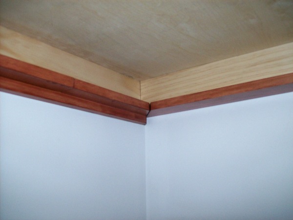
Here is the far right corner. You can see the rail on the left is in
the normal orientation whereas the one on the right is upside down. The
mounting surface is flush. This is the underside of section B.
|
|
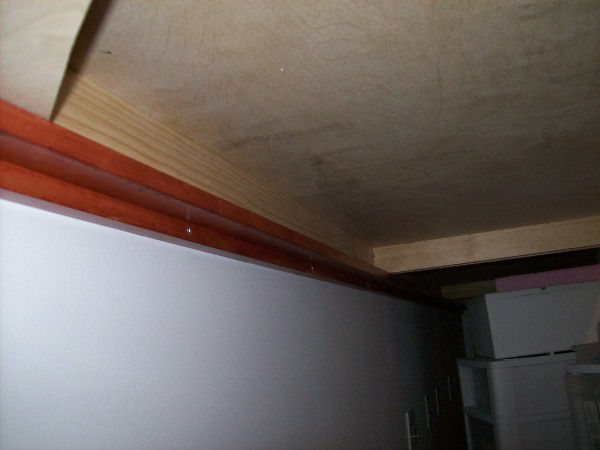
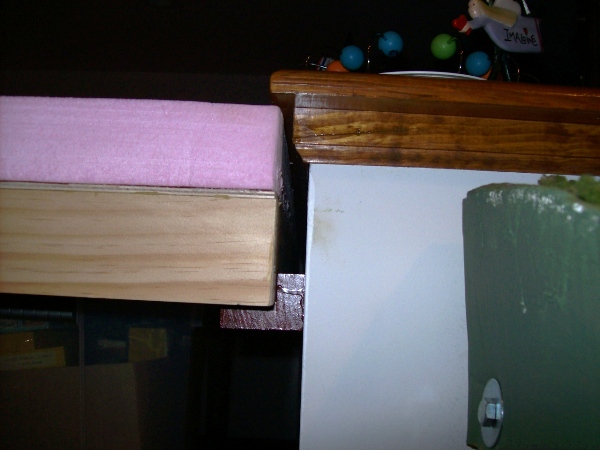
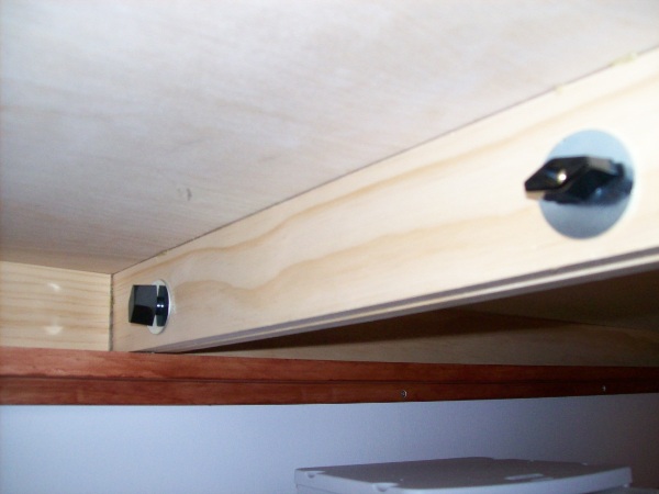
Here you can see the end of the upside down rail and how it forces
section A away from the wall so that it clears the shelf's molding.
There is about 1/8" room underneath the lip of the shelf and the height
of the framing, plywood and foam is 4.75".
The green board on the right is the side of the GS&SV railroad.
|
|
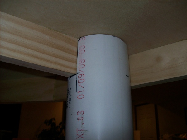
Next up was leg construction. What we have here is 4" PVC sewer pipe.
Home Depot cut each of the three 10' pieces I bought into 3 equal
pieces 40" long. They didn't need to cut too accurately because I needed
about 36" pieces. These were about $2.50 a leg ($7.50 for the 10'
piece).
These are vertical, the camera has distorted them.
|
|
I cut a notch out of the top to attach it to the benchwork. The
notches were either one, two or three widths of the 1"x3" pine wide and
approximately 3" high.
With the layout sections being attached to the
wall rail (well they are not yet, but will be) and them being bolted
together (again, that's up and coming), I not not sure that these legs
actually need to be attached firmly to the benchwork. The 4" width makes
them nice and stable, especially when the benchwork is fixed in place.
|
|
This one is between sections E and D. The notch is two board widths.
|
|
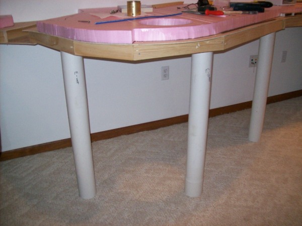
Jumping ahead to the completion, here are the 8 legs in place and
they have been covered in "fake wood" contact paper. One roll, 24'
long and 18" wide was enough for 7 legs, so I needed two. Those were
$6.50 each, or $1.63 per leg.
That means my per-leg cost was just a little over $4 each. Not too
bad!
|
|
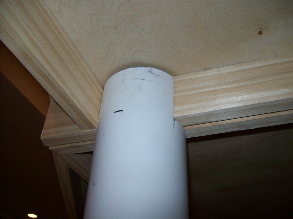
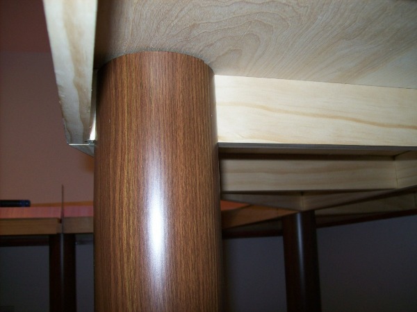
Here's a close-up of one of the contact paper covered legs. It looks
really quite good!
I applied it to the pipe by laying it flat on the
slate top of my pool table and rolling the pipe over it whilst pressing
down hard.
Oh, and before all of this, when I was measuring the pipe for size, I
again used my smart level to get everything as close to 0.0 degrees
level as possible. Mostly everything is within 0.1 degrees of level.
BTW, this leg is the center leg of section A.
|
|
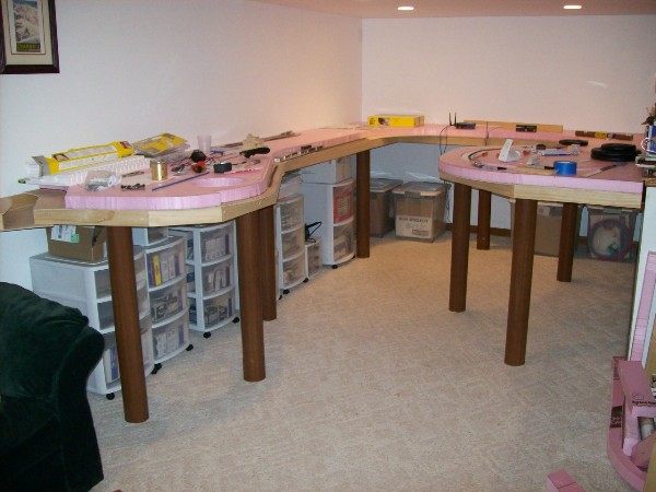
I've now put all of my train stuff storage bins under the layout. I
like this open look with these legs.
|
|
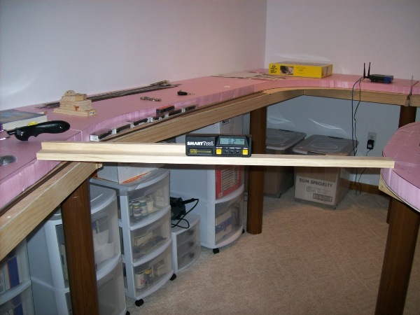
A quick measurement shows my cross-layout slope as 0.2 degrees. On
the track that will be approximately 25' of track between those points
which makes it a nominal ruling grade of not very much! Maybe if the
piece of wood was longer (it only just got from side to side), I'd find
it's less than 0.2 degrees.
|
|
For each of the section joints, I have a pair of 1/4x20 bolts (either 2" or 2.5" in length) that I have a tab knob for tightening.
This makes it both easy and quick to assemble and disassemble them.
This is the joint between sections D and E.
The bolts were 23 cents, as were the washers, at ACO Hardware.
Initially I had, you guessed it, 23 cent thumbscrew fasteners (wing nuts) on the
end. However, I liked the look of the $2.25 tab knobs much better. Plus
they are much easier on the fingers to loosen or tighten.
Finally, the end of section E, which is just over 15' from the corner of section C, needed to be secured to the
wall because it's natural tendency was to be about 1/4 out from the wall.
What I did here was sink a hangar bolt into the very end wall stud and drill a larger hole into the side of section E.
A hangar bolt has a wood screw on one end and a bolt thread on the other. I picked a 2" bolt that had about 1" of
wood screw followed by a smooth length of about 1/2" and then 1/2" of 1/4x20 bolt thread.
I capped it off with another tab knob. Everything is now very secure.
|