|
| |
Power Distribution
|
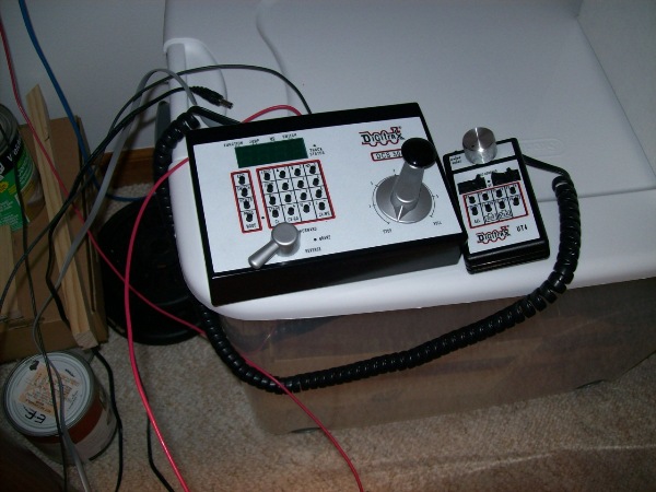
Original DCC system:
- Digitrax Zephyr (DCS-50). 2.5A output, 12 locomotive slots
(left).
- Digitrax UT-4 infrared throttle (right)
Digitrax Manufacturer's Website.
|
|
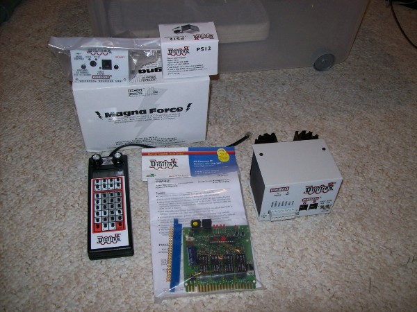
Replacement DCC system:
- Digitrax Radio Super Chief (DCS-200). 8A output, 120
locomotive slots (front, right).
- DCC Specialties' Magna Force MP-615 power supply (back,
center)
- Digitrax PS-12 power supply (back, top, right)
- Digitrax UR-91 radio receiver (back, top, left)
- Digitrax DT-400 radio throttle (front, left)
- Digitrax PM-42 power management module (front, center)
Digitrax Manufacturer's Website.
DCC Specialties Manufacturer's Website.
|
|
The Magna Force provides the power for the DCS-200 booster which can draw up to 8A.
That's quite a lot of power which needs to be safely provided.
So, I decided that I needed to fuse the power supply in front of the booster. PLus, I wanted a readily
accessible on/off master switch. And, finally, I wanted easy connectivity, i.e. not having to get a
screwdriver to disconnect the power supply.
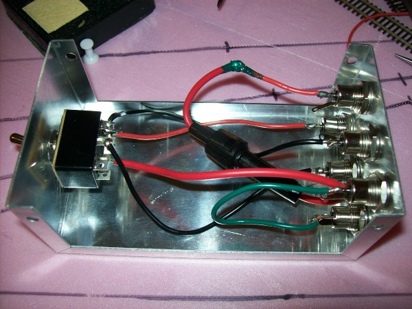
I went off to RadioShack, bought an enclosure, switches, connectors and a 8A quick blow fuse.
Here's the inside of what I put together.
I used the center conductor pin of each connector only since the case is conductive (and, you can
see with the green wire, also earthed).
|
|
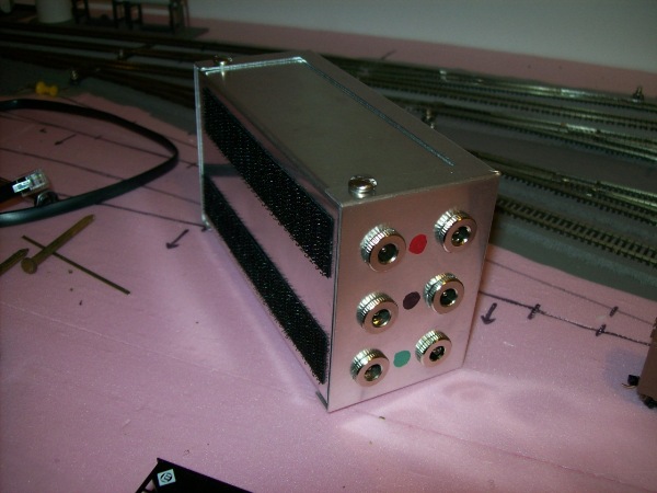
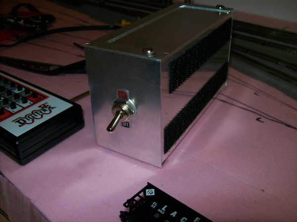
Here's the rear view, inputs from the Magna Force on the left and outputs to the DCS-200 booster
on the right. Velcro also helps to secure the box in place.
|
|
Here's the front view showing the master switch. Turning this off cuts the power to
the booster.
|
|
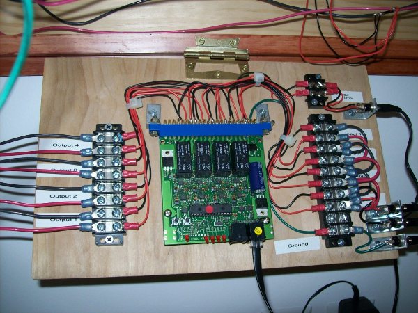
From the switch and fuse box, the power is routed to the DCS-200 booster. There are three wires from
the booster, rail A, rail B and ground. These connect to the board that I created to house the PM-42
power distribution module.
Those connections are to the right terminal strip. Shown here,
the board is being tested and small wires are connected to input
#1 on the center right and to the ground at lower right. A
single output (#4) is being tested on the left.
|
|
The four outputs from the PM-42, for the four power districts, are
then connected to the layout at the layout distribution point.
This is the point (or terminal strip) from which the layout's power
buses run.
The four outputs correspond to the four power districts:
- Main Lines
- Engine Service Facility
- Yards
- Branch Lines
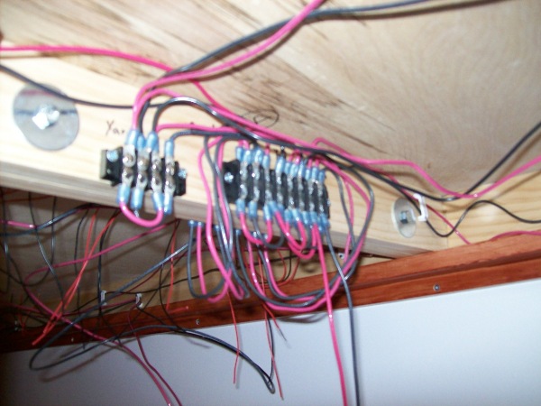
The distribution point is show here prior to the installation of the PM-42 board. The center
terminal strip receives the 4 input pairs (rail A is red, rail B is black) on the lower side, which is seen
here with the input to the first pair on the right (from below) and this power jumpered to the other
3 inputs. The module joint is between modules C and D.
|
| More to come.... Last updated October 20th. |
|