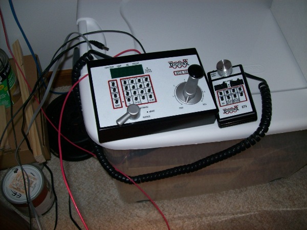
Power comes from the MF615 to the DCS-200. In the red wire, there is a master
switch which is in a spot that will be accessible under the facia.
From the DCS-200, which is set to the N-scale setting (12 volts), the booster output is routed to the
PM-42, between which there is also am 8 amp fast-blow fuse. Overkill? Maybe. But, although the DCS-200
is rated for a maximum output of 8 amps, there should not be anything that can cause more to hit the PM-42
with this fuse in the way.
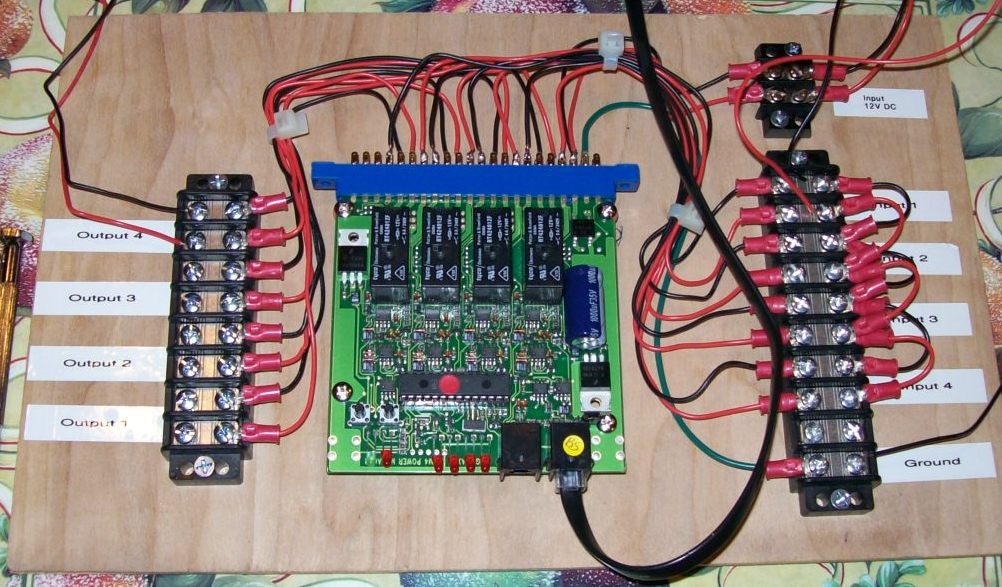
From the PM-42 come the 4 outputs, one to each power district's power bus. The trip current can be set for the PM-42
at currents from 1.5 amps to 12 amps in 1.5 amp increments. The setting applies to all outputs. I have
initially set it to 1.5 amps although this may need to be raised to 3 amps. Each output of the PM-42
could be used as a reversing unit instead. I am not using that functionality, instead using
Digitrax AR-1 auto-reversing units where necessary. You can see more
on the PM-42 below.
The power bus for each district is 14 gauge solid wire. I have a red wire and a black wire throughout. This
wire was purchased at Home Depot at 18 cents per foot. If I had been smark, I would have bought 500 foot reels
of each for $35 each because I would have spent only a few bucks extra but would have had about 250 feet spare
for expansion in phase II of the development. Oh well.
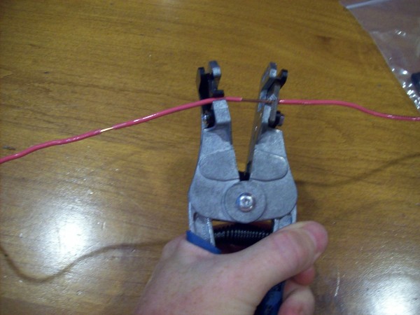
From the power bus, there are track feeders, also red and black, this time in 22 gauge solid. These are
limited to about 12 inches in length. There is a track feeder to pretty much every single piece of track. That's
a lot of feeders but it does mean I should not suffer from voltage drop issues. I like the solid wire because I feel it is
easier to bend and solder to the track.
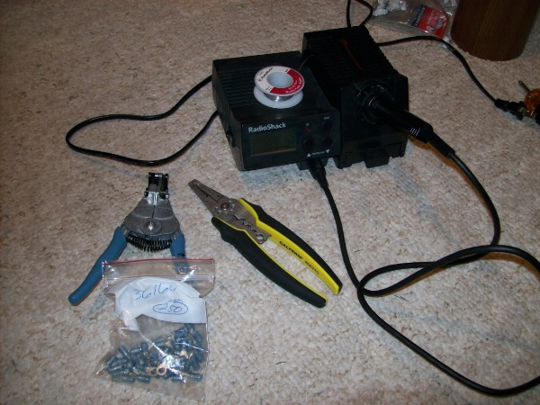
The PM-42 is a pain to wire because it involves soldering a whole bunch of wires. Also, the gauge of wire
needs to be reasonably small because of the small size of the holes in the board connector. Whereas, I have selected 14 gauge
for the buses, the PM-42 has forced me to use (short lengths of) 22 gauge wire. These go to/from terminal strips which, with the
PM-42, are mounted on a small board. This board is hinged to the bottom of the "C" module.
From the board, the bus wire goes to the main distribution point, from which the buses run around the modules.
Inter-module gaps are bridged with terminal strips. Initially, I used
Molex connectors, but decided that, although there was
an extract connection at the inter-module gaps, the solution was both neater, and, IMHO, less prone to problems.
Under the main yard, there are actually two separate buses for the yard. These originate from the same point on
the main distribution terminal strip and allow for shorter feeder wires. Similarly, under module A, there are two
for the main line.
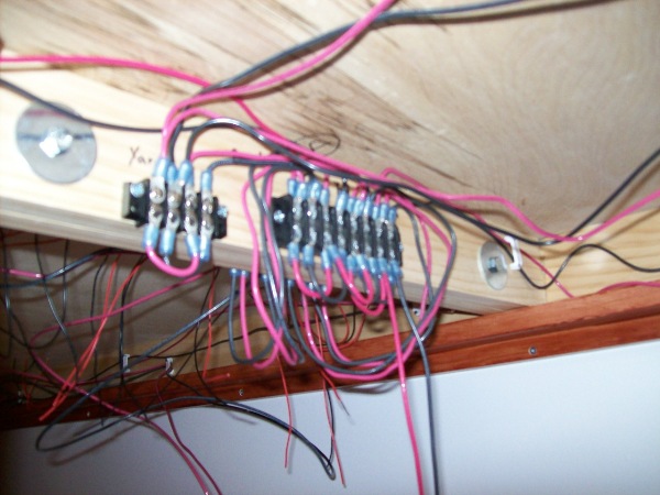
The photo two above shows the main distribution point, prior to the
installation of the PM-42. Power arrives on the bottom of the
terminal strip at the right. Jumpers provide power to the other 3
districts temporarily. This is on module C at the module C/D
boundary. Note the spider web appearance. This is because a number
of feeder wires have not been arranged and soldered to the
appropriate bus on the D module.
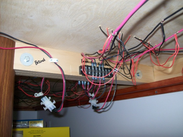
The next photo shows the module B terminal strip at the B/C
module boundary. This shows the terminal strips plus the original
Molex connectors. The Molex connectors will be upgraded to the terminal strips.
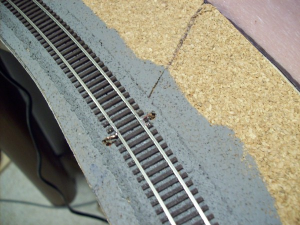
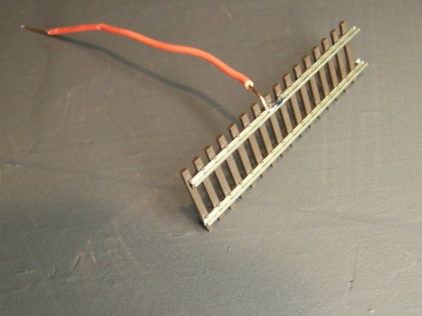
The third photo shows a pair of track feeders on the branch line.
These will be painted and hidden in the ballast.
|
 The layout will run with DCC control only.
